Dies ist eine alte Version des Dokuments!
Inhaltsverzeichnis
Adding WiFi-control to a Venta LW45 humidifier
1. Why adding WiFi to a traditional humidifier
In our appartment, we are using a Venta LW45 air humidifier during the winter to increase air humidity to acceptable levels. These humidifiers follow a very simple principle: Several rotating disks are put into the water and a ventilator blows air through the device. The humidifier has three operating levels (1-3) and signals an error if the water reaches a low level.
Now, since I have ZigBee temperature and humidity sensors in every room, I wanted to automate the humidifier and write rules in OpenHAB that would turn on the humidifier whenever the humidity falls below a threshold and also turn it off again once an acceptable level is reached.
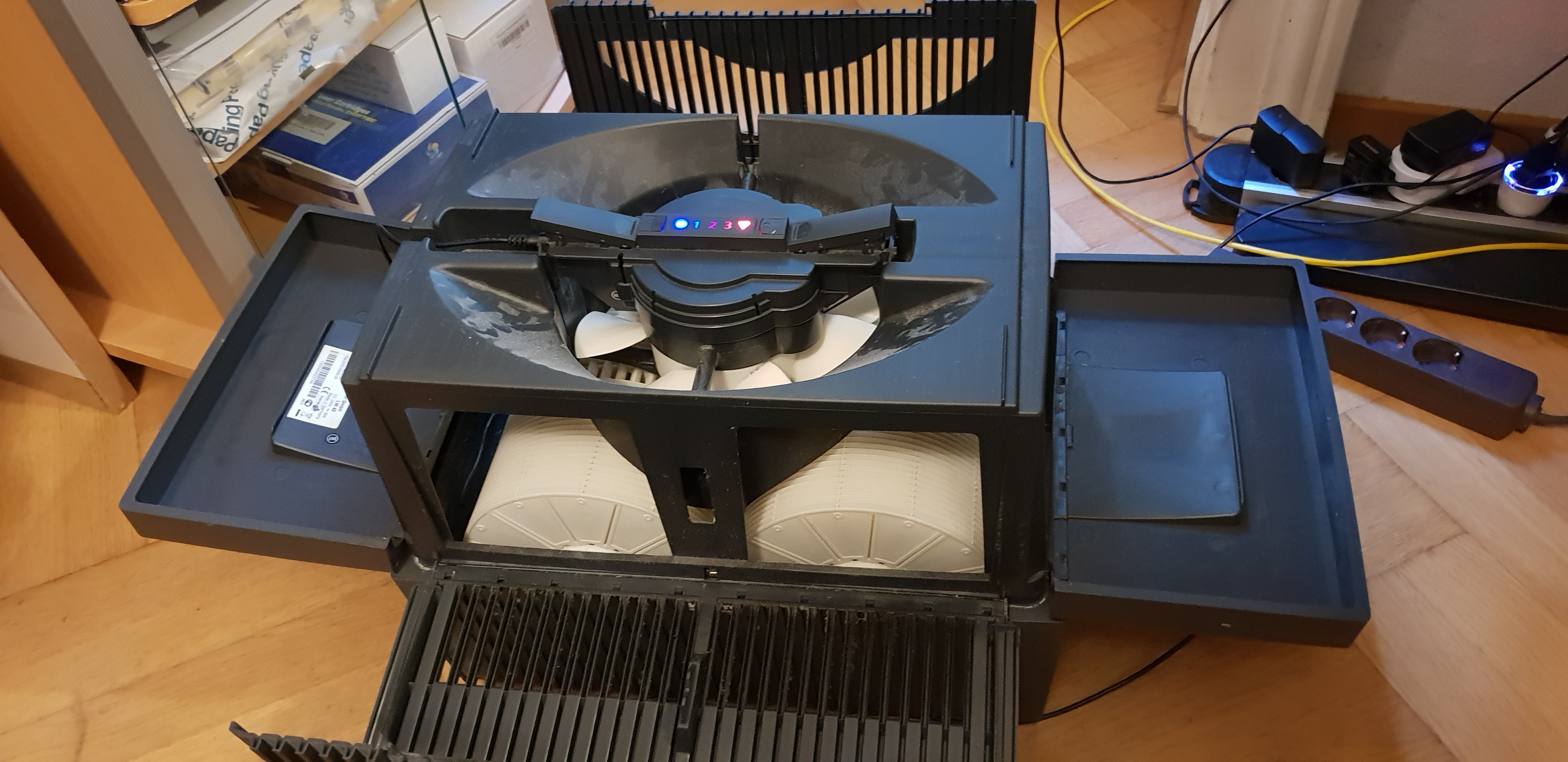
2. Investigating the electronics of the LW45
Previous versions of the Venta humidifier (LW14, LW24, LW44) are simply using a 220V motor with a manual switch that changes between different resistor values to control the speed of the motor. With their current generation of humidifiers (LW15, LW25 and LW45), the Venta devices control the motor through a microchip-based electronic control board with two buttons to turn the device on/off and to change level by one.


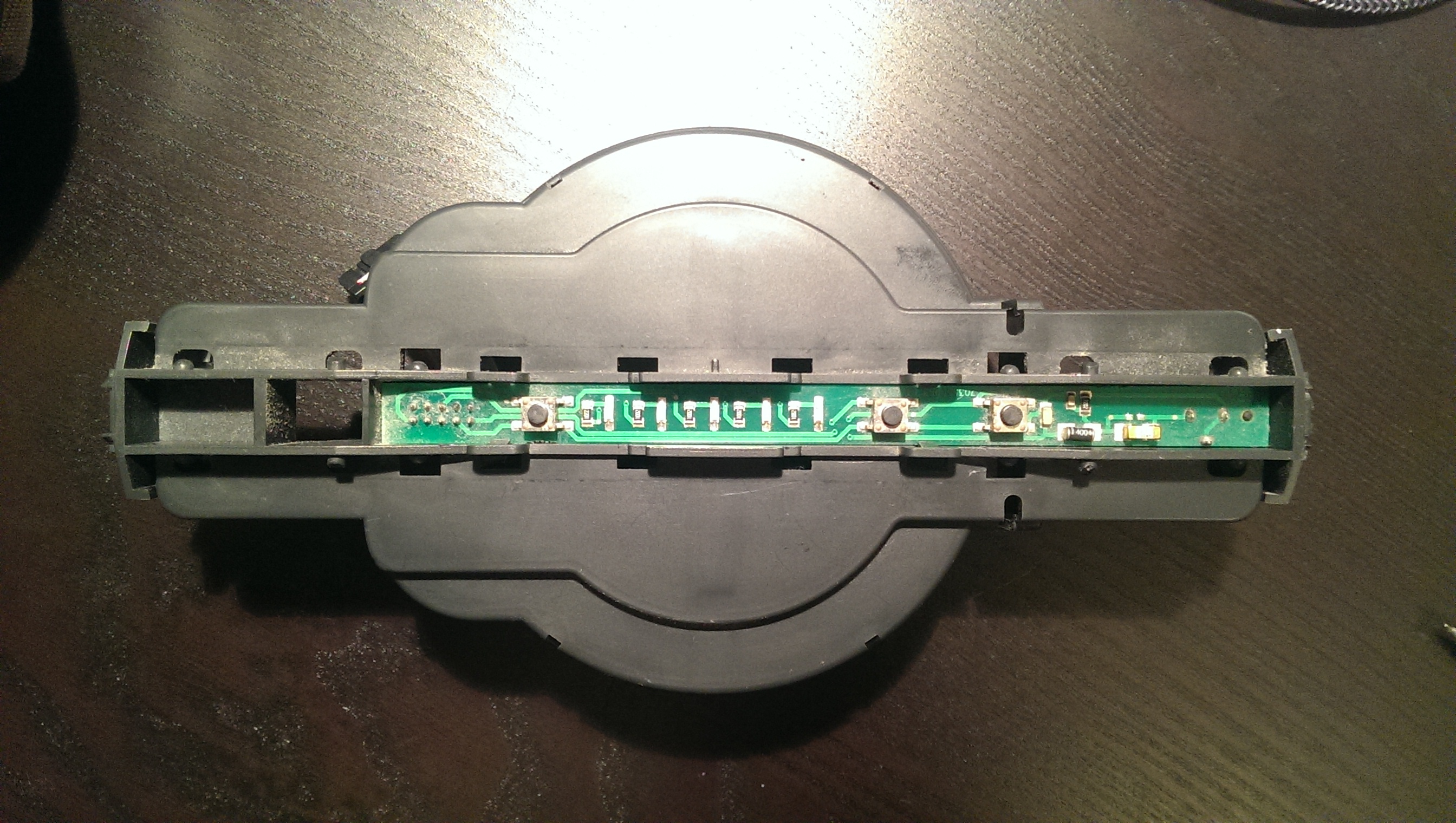
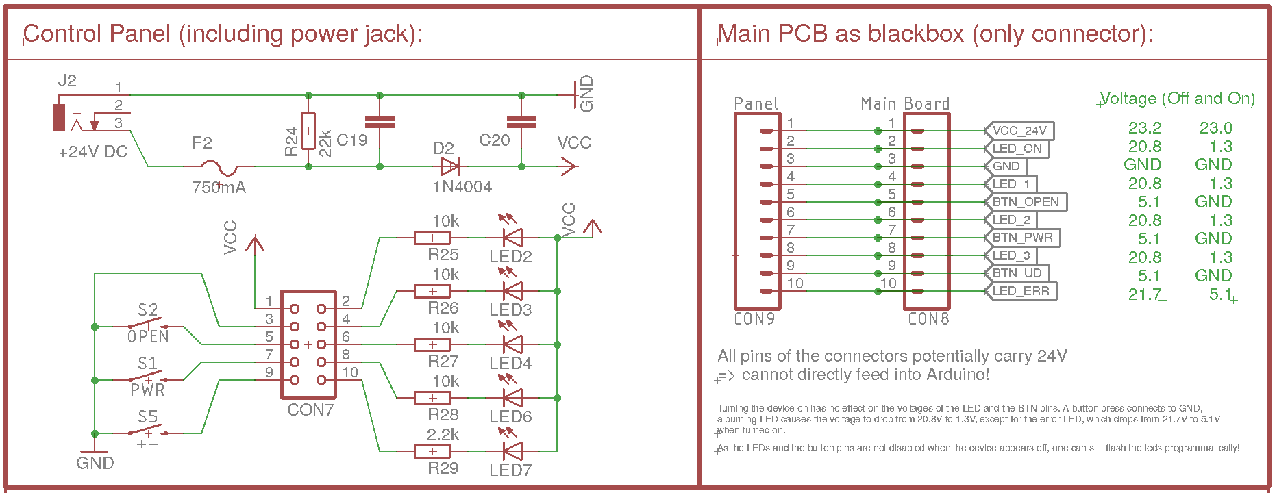
Opening the device shows the main PCB, which is connected to a control panel (with switches and LEDs visible at the upper side of the humidifier) through a 10-pin IDC flat band cable. The power supply is a 24V external power supply that is plugged into the control panel. The schematics of the control panel is as follows:
The control panel has the following features:
- Four LEDs indicating Power On, the level (1-3) and a red error LED. All of them are controlled by the main PCB by pulling the corresponding pin of the connector to low
- To detect current power status, level and error status, one can simply read out the pins of the connector.
- To light up a LED, the corresponding PIN needs to be pulled to GND.
- The power and level buttons simply connect the corresponding pin of the connector to GND.
- The sensor to detect an opened device is implemented as another button, which again connects to GND when the device is opened.
3. How to implement the different parts hardware-wise
Looking at this schematics, it is apparent how a WiFi control can be easily added to the LW45 humidifier:
- Insert a WiFi-enabled PCB between the main PCB and the control panel
- That PCB would read out pins 2, 4, 6, 8 and 10 of the cable/connector to detect the power status, level and error status.
- To turn the device on/off or switch levels, the pins 7 or 9 are connected to GND by the microcontroller.
- To detect an opened device, pin 5 is read (GND means device open)
- To light up the error LED, pin 10 need to be pulled to GND.
All these steps can be easily done by any microcontroller used in smart home applications. The only problem is the power: The VCC is 24V and the levels of the LED pins are potentiall 24V!
3.1 Power supply: Step-down converter from 24V to 3.3V
Initially, I tried a normal LN7805 voltage regulator, but that heated up too much, especially considering that the WiFi-PCB would be placed inside the humidifier inside the plastic enclosure with very little air flow. Instead, I'm using a 24V to 3.3V step-down converter.
3.2 Microcontroller and WiFi connection
 Initially, I planned to use an ATmega328P microcontroller (5V) and a NRF24L01+ module to connect the Venta to a MySensors gateway. I completed a schematic and even built a prototype on a breadboard and wrote the corresponding code. However, I finally decided to instead directly connect the Venta LW45 to our WiFi network, so I would not depend on the MySensors gateway and could directly control the device.
I switched over to an ESP8266-12F module that is SMD-soldered on the PCB. The ESP needs the usual pull-up resistors on EN, reset and GPIO0 to properly boot as well as the pull-down on GPIO15. To program it, we add the usual two buttons (Reset and boot on the reset and GPIO0) and also add the usual 100nF capacitor between 3V3 and GND near the ESP.
The pull-down R19 and pull-up R17 are dashed, as they are also used as pull-down and pull-up for the power button emuation and the LED 1 detection.
3.3 Detecting LED status
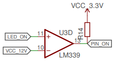 The pins that are connected to the LED are pulled low (to GND) when the LED is lit and are either >20V or at ~5V when the LED is turned off. To detect the LED status, one only needs to read out the voltage of the pin. Unfortunately, both 20V and even 5V is too much to feed into the ESP8266 directly. Instead, a comparator like the LM339 or LM393 can be used to compare the voltage of the pins with a refence voltage of 12V (generated with a voltage divider from the 24V VCC) or 3.3V VCC for the error LED.
The output of the comparator is pulled high with a pull-up resistor to prevent a floating state, as the comparators are open collector (i.e. they do not feed any voltage in HIGH state, but pull the output to GND for LOW state ⇒ The output can be used for any voltage/logic level required).
The pins that are connected to the LED are pulled low (to GND) when the LED is lit and are either >20V or at ~5V when the LED is turned off. To detect the LED status, one only needs to read out the voltage of the pin. Unfortunately, both 20V and even 5V is too much to feed into the ESP8266 directly. Instead, a comparator like the LM339 or LM393 can be used to compare the voltage of the pins with a refence voltage of 12V (generated with a voltage divider from the 24V VCC) or 3.3V VCC for the error LED.
The output of the comparator is pulled high with a pull-up resistor to prevent a floating state, as the comparators are open collector (i.e. they do not feed any voltage in HIGH state, but pull the output to GND for LOW state ⇒ The output can be used for any voltage/logic level required).
3.4 Emulating a button press
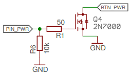 A button press can be simulated by shortly pulling the corresponding pin low and releasing it. This is exactly what the mechanical buttons on the control panel are doing. Again, the voltage is too high feed directly through the ESP8266, so we are using a FET transistor to connect the pins to GND whenever the ESP sets its output pin to high. During startup of the ESP, the FET would be floating (and thus might cause a button press), so we pull the ESP output pins to GND with a high-valued resistor. Additionally, I added a small gate resistor to make sure there are no issues when the FET switches.
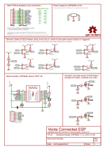
3.5 The full Schematics
Putting all pieces together, the schematics of the PCB looks as following:
The partlist is as follows:
| Part | Description | Size |
|---|---|---|
| C2 | 0.1uF capacitor SMD | C0805 |
| J1 | 2x5pin boxed header male | 2.54mm through-hole |
| J2 | 2x5pin female header | 2.54mm through-hole |
| Q1, Q4, Q5 | 2N7000 transistor SMD | SOT23 |
| R1, R2, R3 | 47R resistor SMD | R0805 |
| R4, R5 | 1M resistor SMD | R0805 |
| R6, R7, R8, R9, (R10), (R13), (R14), R15, R16, (R20), (R21) | 10k resistor SMD (some optional) | R0805 |
| R18 | 470R resistor SMD | R0805 |
| SW1, SW3 | Tactile switch SMD | 6×3.5mm |
| U2 | 24V to 3.3V Buck converter | through-hole |
| U3 | LM339 comparator SMD | SO14 |
| U4 | LM393 comparator SMD | SO08 |
| X2 | ESP-12e wlan module and microcontroller (SMD-mounted) | |
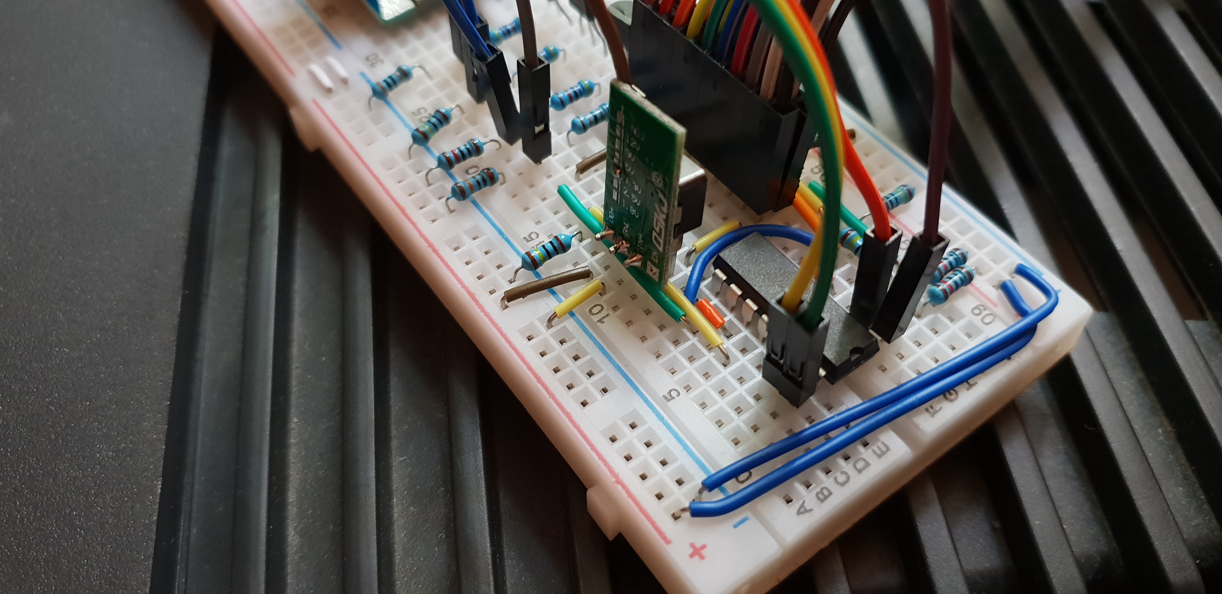
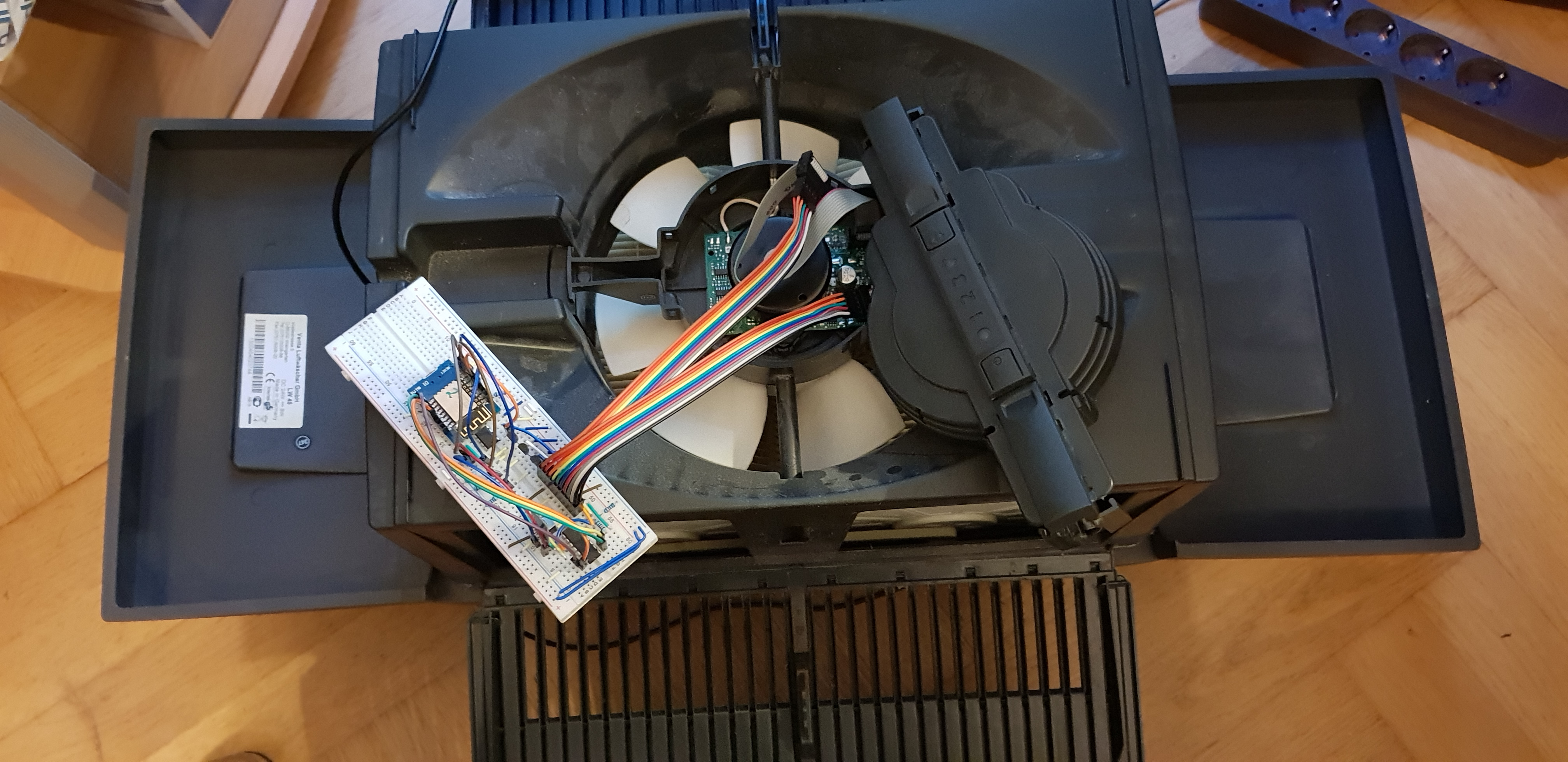
4. Building a prototype on breadboard
Now that we have designed the schematics of the circuit, let's put them to the test by building a prototye on a breadboard and testing it with the humidifier. Here are some images of the breadboard that I built (in various versions, because the LM339 comparators took too long to arrive, so I temporarily used two resistors voltage dividers instead):


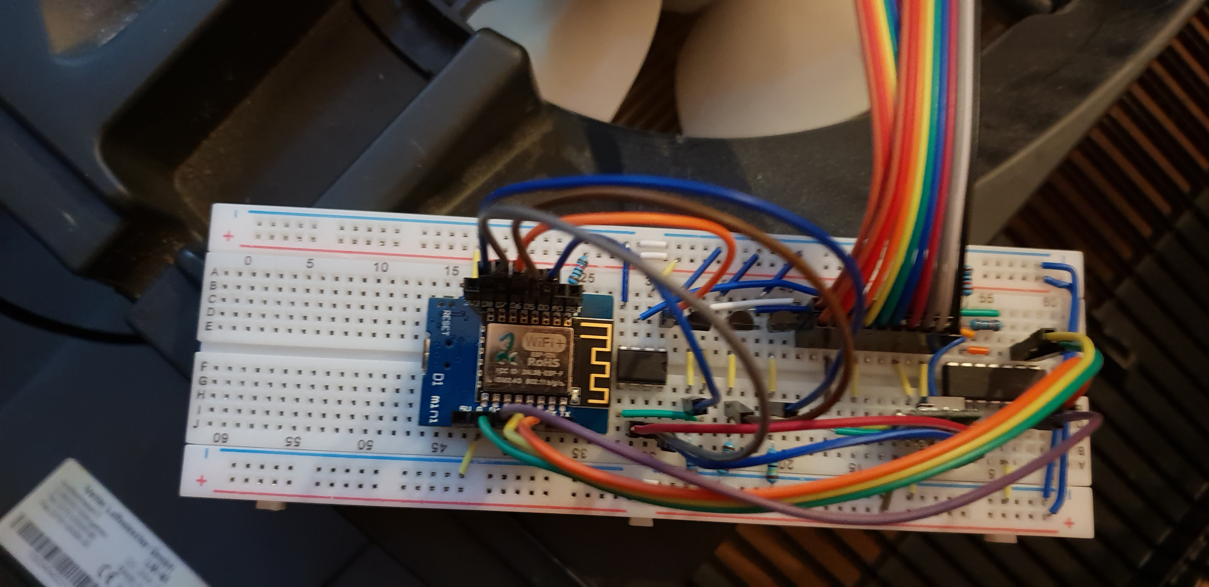

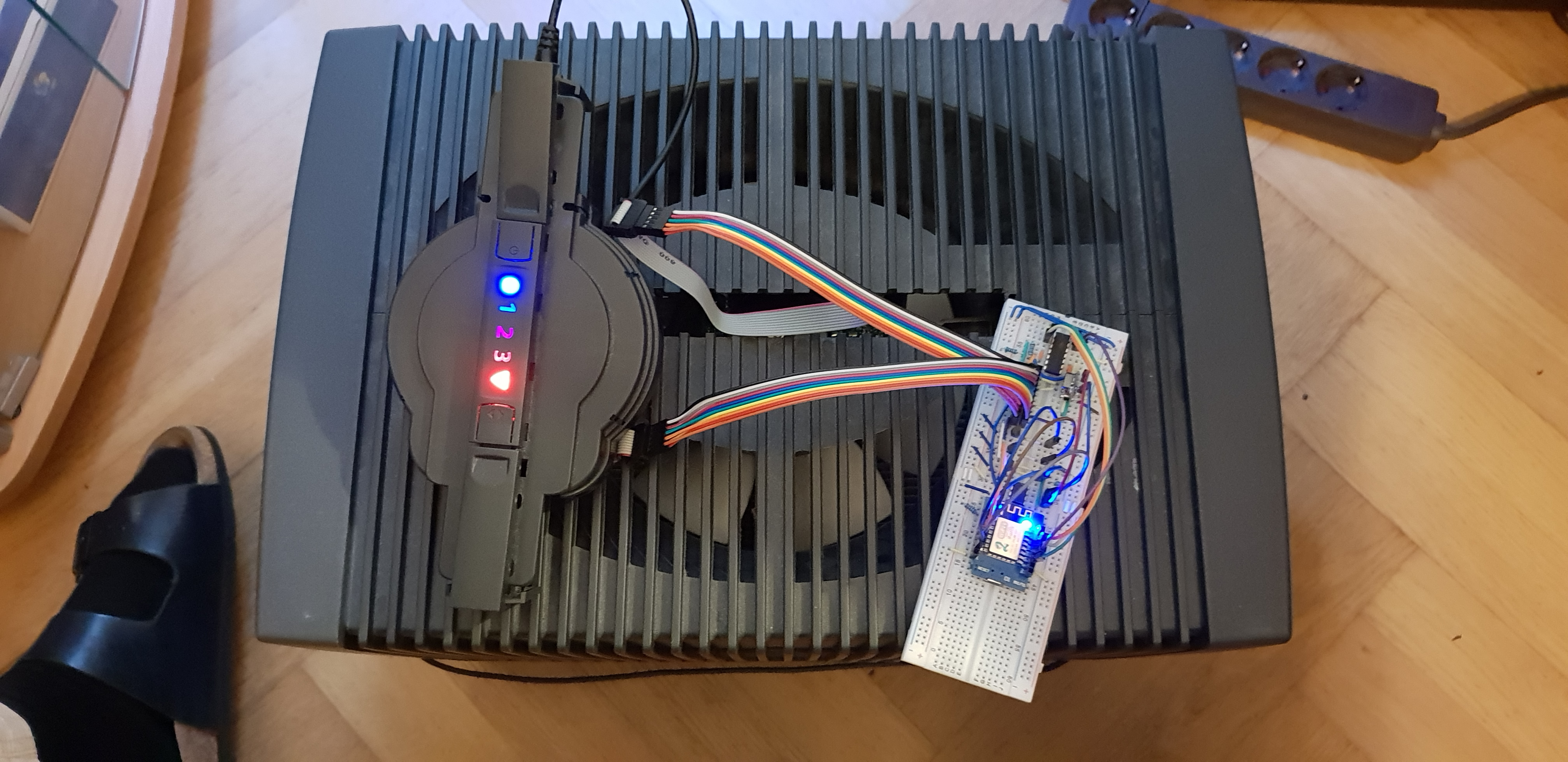
And voila: It works perfectly:
5. Designing the PCB
The next obvious step is to design a nice PCB to fit into the motor enclosure and produce the final board.


The final version of the PCB has not yet arrived, but a previous version (using „normal“ transistors instead of FET) looks like this:


After soldering all components, the PCB can be plugged into the 10-pin IDC connector of the main board of the Venta humidifier, just between the main board and the cable that connects it with the control panel:

6. Firmware for the ESP8266: ESPEasy
Since we now have the hardware working, we need some software on the ESP8266 chip to control the Venta LW45 humidifier. Instead of writing a proper control firmware from scratch, I decided it was most comfortable to use the existing ESPEasy firmware firmware for the ESP.
The ESPEasy firmware can easily be flashed through a 6-pin FTDI USB to TTL Serial Adapter (3.3V) with the provided FTDI pin holes. I'm using a self-made pogo-pin adapter with spring-loaded pins, so I only have to press the pogo pins to the PCB to upload rather than soldering pin headers.
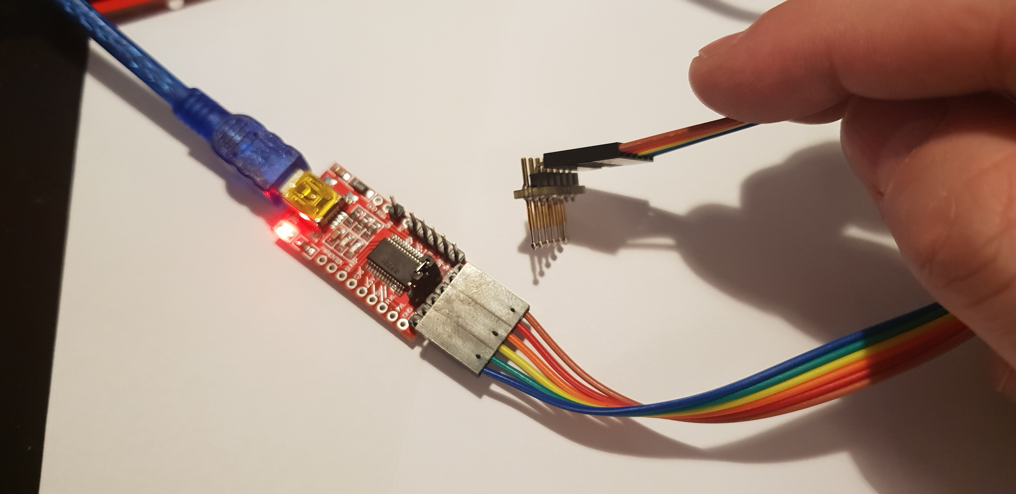

To put the ESP into flashing mode, you need to press the reset button, keep it pressed while pressing the PROG button, release the reset button and after a second or so release the PROG button, too.
6.1 Configuring ESPEasy: General setup
Apart from setting up wireless on the ESPEasy, we need to prepare the hardware pins.
Our schematics has six (digital) input pins for detecting power, level and error, and three output pins to emulate a power button press, an up button press and to flash the error LED.
The full list of ESP pins used by our project is:
| Pin | Purpose | In/Output |
|---|---|---|
| GPIO-2 (D4): | Power LED | (digital) INPUT |
| GPIO-0 (D3): | LED level 1 | (digital) INPUT |
| GPIO-4 (D2): | LED level 2 | (digital) INPUT |
| GPIO-5 (D1): | LED level 3 | (digital) INPUT |
| GPIO-13 (D7): | Error LED | (digital) INPUT |
| GPIO-15 (D8): | Power button press | Switch OUTPUT, default LOW |
| GPIO-14 (D5): | Up button press | Switch OUTPUT, default LOW |
| GPIO-12 (D6): | Case open detection | (digital) INPUT |
| GPIO-16 (D0) | Error LED control | (digital) OUTPUT, default LOW |
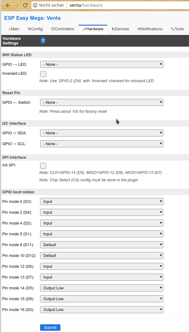
As a first step, the „Hardware“ tab of ESPEasy allows to set the pins we use to either input or output as given in the list above:
6.2 Configuring ESPEasy: The default way
Using only the standard plugins of ESPEasy, all digital inputs can be set up as Switches (device type „Switch input - Switch“). The corresponding Switch variable of the device will then indicate whether the LED is turned on or not.
Similarly, ESPEasy already provides a way to control generic output to a GPIO: https://www.letscontrolit.com/wiki/index.php/GPIO So, to emulate for example a Power button press, one would send the command
Pulse,15,1,100
to ESPEasy. This command means that GPIO 15 is set to 1 (HIGH) for 100 ms and then reset to the default LOW. For details see the GPIO documentation page on the ESPEasy homepage.
6.3 Configuring ESPEasy (advanced): Writing a dedicated Venta plugin
The approach described in the previous paragraph allows to use a stock ESPEasy version on the ESP8266 on the Venta control board. However, it only allows to read out the status of each LED individually, so there is no variable that gives the current level. Similarly, switching the Venta humidifier to a desired level is not straightforward, as the sequence of button presses to switch to a particular level depends on the current power state and the current level. That logic needs to be implemented in the smart home controller with the default way.
In my view, while technically the problem is solved, I don't regard direct GPIO-access as user-friendly or suitable to a device that you want to use in daily life. the WAF (wife-acceptance factor) is just too low. I tend to compare the situation with a TV remote. Technically, switching to a particular channel means you tune your receiver to a given frequency. However, on your remote control you don't have to care about frequencies.
So, rather than exposing the state of individual error and information LEDS and exposing GPIOs for switches, I decided to write a dedicated ESPEasy plugin for the venta humidifiers, which exposes the functionality rather than the technical details. In particular, to a user the humidifier should have the following functionality:
- Report current power status ON/OFF (technically: read the status of the power LED)
- Turn device on/off (technically: toggle the power button)
- Report current level (technically: read out the three level LEDs and report the one that is lit)
- Switch to a desired level (technically: Press the up button until the desired level is reached, unless error LED is on, potentiall press ON before)
- Report Error (technically: read out the status of the error LED)
- Report Case Open (technically: read out the status of the case open button)
- Flash or turn on the error LED (technically: set the GPIO of the error LED to HIGH for a certain amount of time)
The plugin that I wrote can be found at github and needs to be compiled locally (i.e. it is not part of the stock ESPEasy distribution, as its target population is very limited): https://github.com/letscontrolit/ESPEasyPluginPlayground/pull/114
The configuration of the plugin consists mainly of setting the correct GPIO pins:
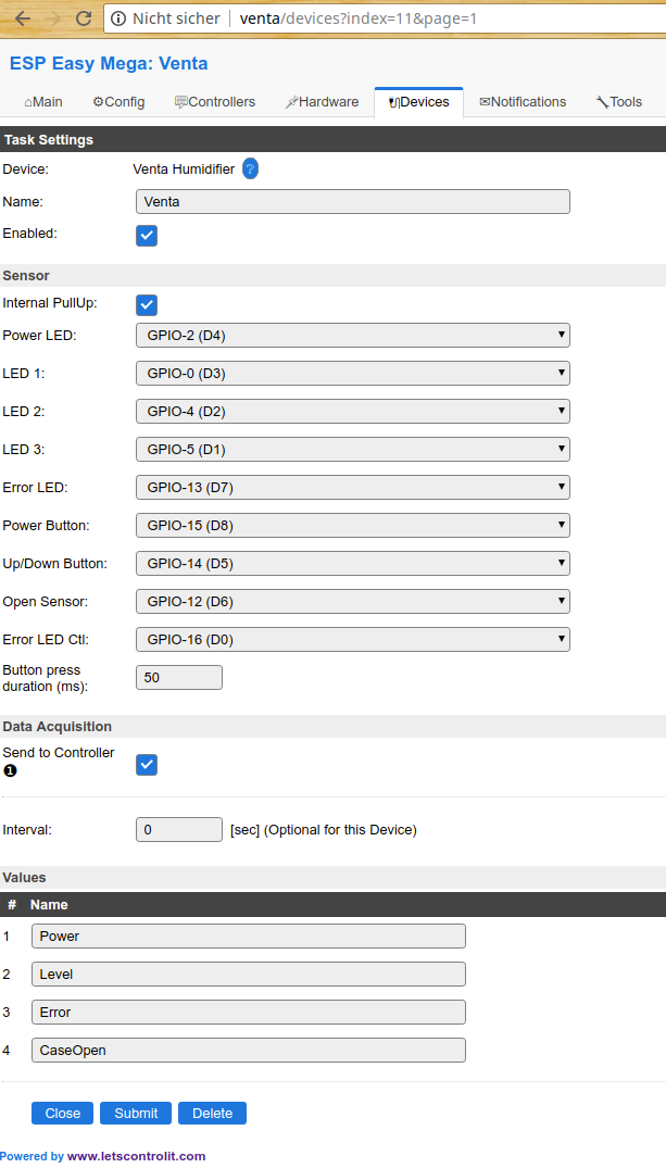 Unless you design your own PCB, the pins shown in this screenshot should be set.
The plugin reports four variables:
- Power: 1 for ON, 0 for OFF
- Level: 1-3 for levels 1-3, 0 for OFF, -1 when error LED is lit
- Error: 1 for Error LED on, 0 for off
- CaseOpen: 1 when case is opened (⇒ error LED is also on), 0 when case is closed)
To control the humidifier, the following commands are provided:
| Command | Description | Arguments |
|---|---|---|
| ventapower STAT | Turn device on/off | STAT=0 to turn OFF, STAT1 to turn ON |
| ventalevel LVL | Switch the power level | LVL=1,2,3 ⇒ switch to level; LVL=0 ⇒ turn off |
| ventapowerbtn | Emulate power button press, irrespective of the current status/level | - |
| ventalevelup | Emulate UP button press, irrespective of the current status/level | - |
| ventaerrorled STAT | Set status of error LED (turning off is not possible, unless is was manually set to ON) | STAT=1 to turn error LED ON, STAT=0 to turn error LED OFF |
| ventaerrorflash DUR | Turn error LED ON for given duration | duration in ms |