Dies ist eine alte Version des Dokuments!
Inhaltsverzeichnis
Adding WiFi-control to a Venta LW45 humidifier
Why adding WiFi to a traditional humidifier
In our appartment, we have used a Venta LW45 air humidifier during the winter to increase air humidity to acceptable levels. These humidifiers follow a very simple principle: A ventilator blows air through the device, while several rotating discs are placed in the water and provide enough water to the airflow through them. The humidifier has three operating levels (1-3) and signals an error if the water reaches a low level.

Now, since I have ZigBee temperatur and humidity sensors in every room, I wanted to automate the humidifier and write rules in OpenHAB that would turn on the humidifier whenever the humidity falls below a threshold and also turn it off again once an acceptable level is reached.
Investigating the electronics of the LW45
Previous versions of the Venta humidifier (LW14, LW24, LW44) are simply using a 220V motor with a manual switch that changes between different resistor values to control the speed of the motor. With their current generation of humidifiers, Venta controls the motor through a fully electronic control board with two buttons to turn the device on/off and to change level by one.


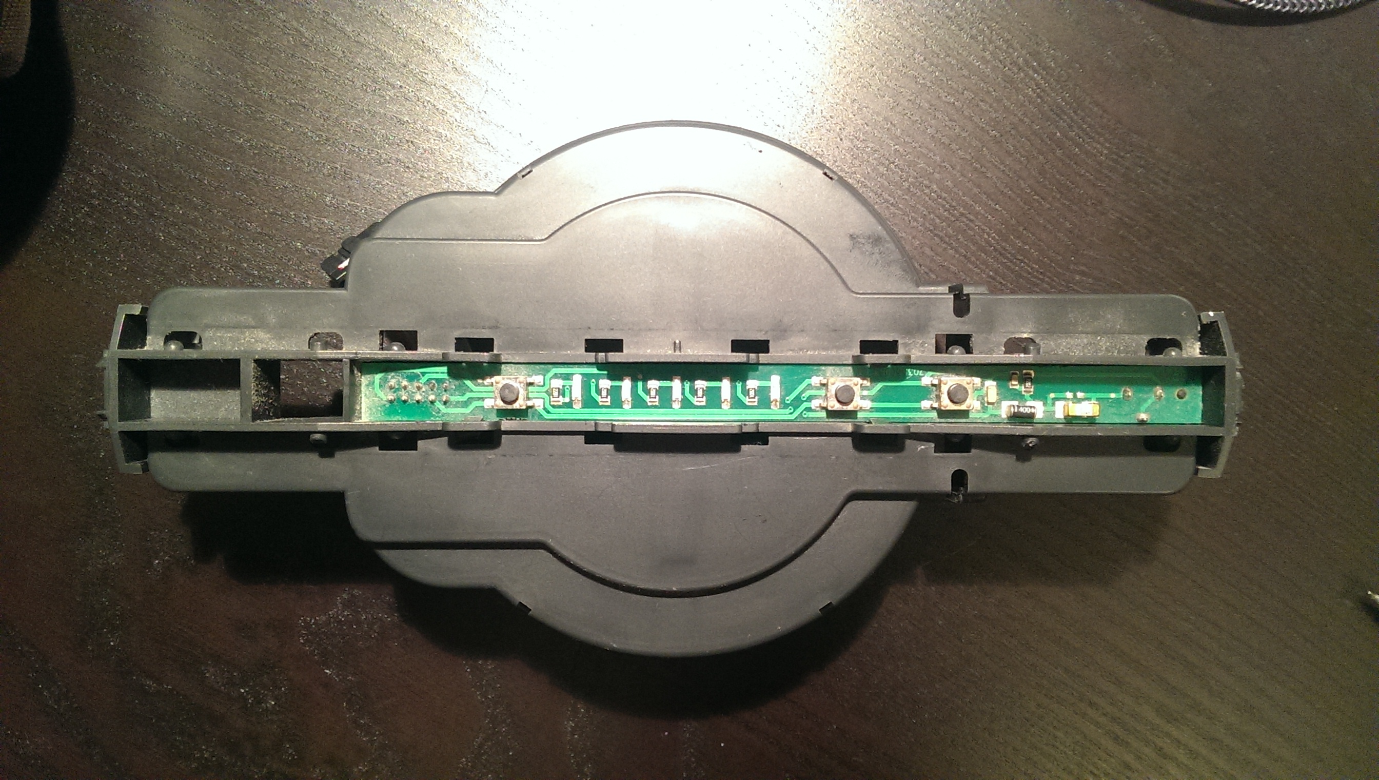
Opening the device shows the main PCB, which is connected to a control panel (with the switches and LEDs visible at the upper side of the humidifier) through a 10-pin IDC flat band cable. The power supply is a 24V external power supply that is plugged into the control panel. The schematics of the control panel is as follows:
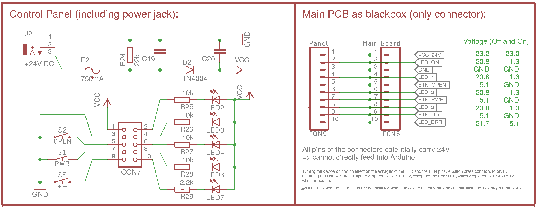
The control panel has the following features:
- Four LEDs indicating Power On, the level (1-3) and a red error LED. All of them are controlled by the main PCB by pulling the corresponding pin of the connector to low
- To detect current power status, level and error status, one can simply read out the pins of the connector.
- To light up a LED, the corresponding PIN needs to be pulled to GND.
- The power and level buttons simply connect the corresponding pin of the connector to GND.
- The sensor to detect an opened device is implemented as another button, which again connects to GND when the device is opened.
How to implement the different parts hardware-wise
Looking at this schematics, it is apparent how a WiFi control can be easily added to the LW45 humidifier:
- Insert a WiFi-enabled PCB between the main PCB and the control panel
- That PCB would read out pins 2, 4, 6, 8 and 10 of the cable/connector to detect the power status, level and error status.
- To turn the device on/off or switch levels, the pins 7 or 9 are connected to GND by the microcontroller.
- To detect an opened device, pin 5 is read (GND means device open)
- To light up the error LED, pin 10 need to be pulled to GND.
All these steps can be easily done by any microcontroller used in smart home applications. The only problem is the power: The VCC is 24V and the levels of the LED pins are potentiall 24V!
Power supply: Step-down converter from 24V to 3.3V
Initially, I tried a normal LN7805 voltage regulator, but that heated up too much, especially considering that the WiFi-PCB would be placed inside the humidifier inside the plastic enclosure with very little air flow. Instead, I'm using a 24V to 3.3V step-down converter.
Microcontroller and WiFi connection
 Initially, I planned to use an ATmega328P microcontroller (5V) and a NRF24L01+ module to connect the Venta to a MySensors gateway. I completed a schematic and even built a prototype on a breadboard. However, I finally decided to instead directly connect the Venta LW45 to our WiFi network, so I would not depend on the MySensors gateway and could directly control the device.
So, I switched over to an ESP8266-12F module that is SMD-soldered on the PCB. The ESP needs the usual pull-up resistors on EN, reset and GPIO0 to properly boot as well as the pull-down on GPIO15. To program it, we add the usual two buttons (Reset and boot on the reset and GPIO0) and also add the usual 100nF capacitor between 3V3 and GND near the ESP.
The pull-down R19 and pull-up R17 are dashed, as they are also used as pull-down and pull-up for the power button emuation and the LED 1 detection.
Detecting LED status
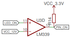 The pins that are connected to the LED are pulled low (to GND) when the LED is lit and are either >20V or at ~5V when the LED is turned off. To detect the LED status, one only needs to read out the voltage of the pin. Unfortunately, both 20V and even 5V is too much to feed into the ESP8266 directly. Instead, a comparator like the LM339 or LM393 can be used to compare the voltage of the pins with a refence voltage of 12V (generated with a voltage divider from the 24V VCC) or 3.3V VCC for the error LED.
The output of the comparator is pulled high with a pull-up resistor to prevent a floating state, as the comparators are open collector (i.e. they do not feed any voltage in HIGH state, but pull the output to GND for LOW state ⇒ The output can be used for any voltage/logic level required).
The pins that are connected to the LED are pulled low (to GND) when the LED is lit and are either >20V or at ~5V when the LED is turned off. To detect the LED status, one only needs to read out the voltage of the pin. Unfortunately, both 20V and even 5V is too much to feed into the ESP8266 directly. Instead, a comparator like the LM339 or LM393 can be used to compare the voltage of the pins with a refence voltage of 12V (generated with a voltage divider from the 24V VCC) or 3.3V VCC for the error LED.
The output of the comparator is pulled high with a pull-up resistor to prevent a floating state, as the comparators are open collector (i.e. they do not feed any voltage in HIGH state, but pull the output to GND for LOW state ⇒ The output can be used for any voltage/logic level required).
Emulating a button press
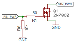 A button press can be simulated by shortly pulling the corresponding pin low and releasing it. This is exactly what the mechanical buttons on the control panel are doing. Again, the voltage is too high feed directly through the ESP8266, so we are using a FET transistor to connect the pins to GND whenever the ESP sets its output pin to high. During startup of the ESP, the FET would be floating (and thus might cause a button press), so we pull the ESP output pins to GND with a high-valued resistor. Additionally, I added a small gate resistor to make sure there are no issues when the FET switches.
The full Schematics
Putting all pieces together, the schematics of the PCB looks as following: ventaconnected_esp8266_v1.0_2018-10-06.pdf