Inhaltsverzeichnis
Vaillant CalorMatic 340f (868MHz) PART 2: Decoding the wireless protocol of the heating control
After we investigated the wireless signal that was sent by the Vaillant CalorMatic 340f over the 868MHz frequency and extracted the binary contents in the first part of our series, this second part will now deal with understanding the meaning of the bits and bytes sent to the boiler.
As a quick recap of the first part, the signal from the wireless control is sent at 868.275MHz with OOK modulation. The underlying encoding is differential Manchester encoding (with a signal bitrate of 606Hz, where a transition in the middle of the period indicates a 1 and no transition indicates 0; a transition after each bit period is guaranteed for clock synchronization and does not hold any information). In addition, the bit sequence (except for the final to 0xFF 00 bytes!) is bit-stuffed, so it starts with 0x7E and after every 5 consecutive 1 bits an extra 0 bit is inserted that has to be removed by the receiver before interpreting the signal.
Features of the wireless control
Let's first look at the features of the wireless heating control:
- Heating modes: Normal and ECO (only different target temperatures)
- Operating modes: Automatic (time-based switch between Normal and ECO), forced Day mode, forced Night mode (=ECO), OFF
- Warm water pre-heating: Up to three different time periods per weekday where the water reservoir in the boiler is kept pre-heated. Outside this period, the water will be heated only on demand.
- Timers (up to three different time periods, independently set for each day) for Normal and for ECO mode
- Current temperature and time is displayed on the screen
- Party mode and override: Overriding the target temperature for a limited time (and/or preventing a switch to ECO mode)
So, the heating and boiler control appears to have some smart logic included. The first question is, whether this logic is inside the wireless control or inside the boiler. In the first case (smart control, dumb boiler), the wireless control would keep the timers and the current state and only signal to the boiler when the heating should be turned on or off. In the second case (dumb control, smart boiler), all information (current temperature, target temperature, date/time, mode, etc.) will be sent wirelessly to the boiler. Of course, the second case would be much more interesting, as this would allow us to later implement a second wireless control that could be implemented e.g. in OpenHAB.
Unfortunately, after sniffing several different target temperatures and several different modes (normal / ECO; Auto/Forced/OFF; Timed pre-heated water on/off), it became clear that the wireless control only sends „Heating ON/OFF“ and „Pre-heated water ON/OFF“ signals to the boiler. In particular, when I increased the target temperature, and the heating was already on, then no signal was sent to the boiler. Also, if the heating was off and I set the target temperature to different values that all caused the heating to come on, the wireless signal was always the same, i.e. the target temperature was never sent to the boiler, but only processed inside the wireless control.
Obtaining all possible signals
I tried all different combinations I could think of (including low batteries!), and the only information that was sent to the boiler appears to be:
- Heating ON/OFF
- Warm water ON/OFF
- Battery OK/LOW
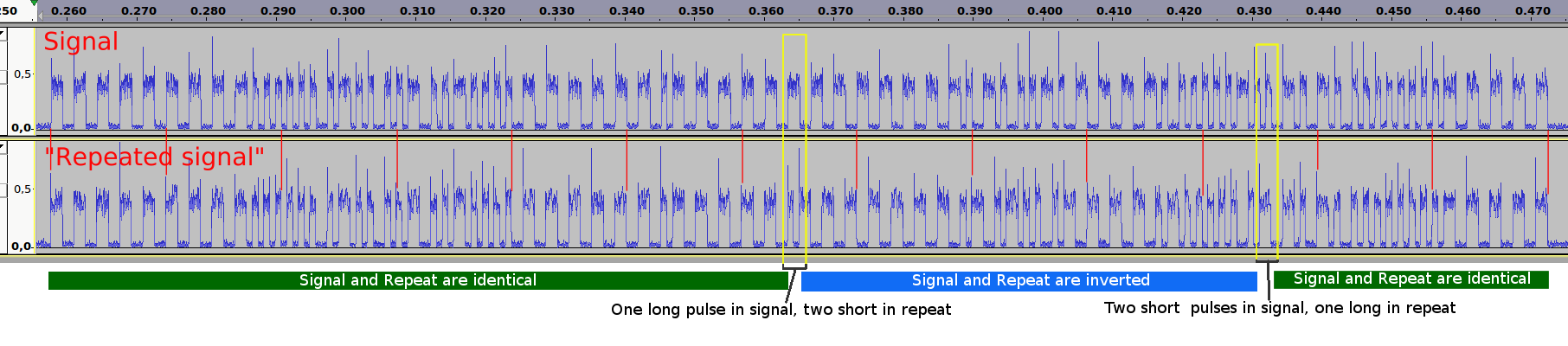
So, there are 8 possible combinations for signals to be sent to the boiler. As we saw in the first part, each signal was followed by a second repeated signal, which has slight differences. So, we have 8 base signals and 8 repeats.
The corresponding observed binary sequences are:
| Description | Signal | |
|---|---|---|
| Heating ON, Water OFF | 00000000 00000000 01111110 10110110 01101111 00000000 00000100 00000000 00000000 00010001 00101101 00000000 10111111 10000010 11111111 00000000 |
|
| Heating ON, Water OFF (Rep.) | 00000000 00000000 01111110 10110110 01101111 00000000 00000100 00000000 10000000 00010001 00101101 00000000 10111111 00000010 11111111 00000000 |
|
| Heating OFF, Water OFF | 00000000 00000000 01111110 10110110 01101111 00000000 00000100 00000000 00000000 00010001 00000000 00000000 10111111 10101111 11111111 00000000 |
|
| Heating OFF, Water OFF (Rep.) | 00000000 00000000 01111110 10110110 01101111 00000000 00000100 00000000 10000000 00010001 00000000 00000000 10111111 00101111 11111111 00000000 |
|
| Heating ON, Water ON | 00000000 00000000 01111110 10110110 01101111 00000000 00000100 00000000 00000000 00000001 00101101 00000000 10111111 10010010 11111111 00000000 |
|
| Heating ON, Water ON (Rep.) | 00000000 00000000 01111110 10110110 01101111 00000000 00000100 00000000 10000000 00000001 00101101 00000000 10111111 00010010 11111111 00000000 |
|
| Heating OFF, Water ON | 00000000 00000000 01111110 10110110 01101111 00000000 00000100 00000000 00000000 00000001 00000000 00000000 10111111 10111111 11111111 00000000 |
|
| Heating OFF, Water ON (Rep.) | 00000000 00000000 01111110 10110110 01101111 00000000 00000100 00000000 10000000 00000001 00000000 00000000 10111111 00111111 11111111 00000000 |
|
| Heat. ON, Water OFF, Batt. LOW | 00000000 00000000 01111110 10110110 01101111 00000000 00000100 00000000 00000000 00010001 00101101 10000000 10111111 00000010 11111111 00000000 |
|
| Heat. ON, W. OFF, Batt. LOW (Rep.) | 00000000 00000000 01111110 10110110 01101111 00000000 00000100 00000000 10000000 00010001 00101101 10000000 10111111 11111100 11111111 00000000 |
|
| Heat. OFF, W. OFF, Batt. LOW | 00000000 00000000 01111110 10110110 01101111 00000000 00000100 00000000 00000000 00010001 00000000 10000000 10111111 00101111 11111111 00000000 |
|
| Heat. OFF, W. OFF, Batt. LOW (Rep.) | 00000000 00000000 01111110 10110110 01101111 00000000 00000100 00000000 10000000 00010001 00000000 10000000 10111111 11001111 11111111 00000000 |
|
| Heat. ON, W. ON, Batt. LOW | 00000000 00000000 01111110 10110110 01101111 00000000 00000100 00000000 00000000 00000001 00101101 10000000 10111111 00010010 11111111 00000000 |
|
| Heat. ON, W. ON, Batt. LOW (Rep) | 00000000 00000000 01111110 10110110 01101111 00000000 00000100 00000000 10000000 00000001 00101101 10000000 10111111 11100010 11111111 00000000 |
|
| Heat. OFF, W. ON, Batt. LOW | 00000000 00000000 01111110 10110110 01101111 00000000 00000100 00000000 00000000 00000001 00000000 10000000 10111111 00111111 11111111 00000000 |
|
| Heat. OFF, W. ON, Batt. LOW (Rep.) | 00000000 00000000 01111110 10110110 01101111 00000000 00000100 00000000 10000000 00000001 00000000 10000000 10111111 11011111 11111111 00000000 |
|
In this table, I already split the binary signal into octets, i.e. bytes.
The individual parts of the signal
All signals start with two 0x00 bytes, which makes perfect sense considering that the physical signal is differential-manchester encoded. The two 0x00 00 bytes simply mean that there will be eight long UP / DOWN impulses, so that the receiver has enough time to synchronize its clock.
The next three bytes 3-5 are also ways the same, but they are not zero. My best guess is that these three bytes are some kind of device ID.
The next three bytes 6-8 are again constant, but mostly full of zeroes. I have not yet found any explanation, so let's just assume they are constant and mostly zeroes.
The next byte 9 varies depending on whether the signal is a repeat or the original signal.
The next byte 10 has different bits for Water ON and OFF.
The next byte 11 is 0 for Heating OFF and has some bits set for Heating ON.
The next byte 12 has one bit set if battery is LOW and is zero otherwise.
The next byte 13 is always the same.
The next byte 14 is the most interesting, as is changes whenever anything before changes. So, this makes it an obvious candidate for a checksum byte. We just need to figure out how that checksum is calculated.
The two final bytes 15-16 are constant and always have the value 0xFF 00, which makes again sense considering the physical encoding, i.e. 0xFF will be a quickly oscillating square ware, and the final 0x00 byte will be a slowly oscillating square wave and not contain any information any more.
Re-writing the signal as HEX bytes
As we already split the binary sequence into bytes, let's rewrite the signal in hexadecimal form, with the least significant bit sent first, i.e. binary 10000000 is hex 0x01 and binary 10010010 is hex 0x49.
Why least significant bit first? That took me a while, too, and it stems from the way the checksum is calculated.
Our sixteen base signals from above now become (again using a little self-written utility):
| Heat. | Wat. | Rep. | Bat. | Byte1 2 3 4 5 6 7 8 9 10 11 12 13 14 15 16 |
|---|---|---|---|---|
| Heating ON | Water OFF | OK | 0x00 00 7E 6D F6 00 20 00 00 88 B4 00 FD 41 FF 00 |
|
| Heating ON | Water OFF | X | OK | 0x00 00 7E 6D F6 00 20 00 01 88 B4 00 FD 40 FF 00 |
| Heating OFF | Water OFF | OK | 0x00 00 7E 6D F6 00 20 00 00 88 00 00 FD F5 FF 00 |
|
| Heating OFF | Water OFF | X | OK | 0x00 00 7E 6D F6 00 20 00 01 88 00 00 FD F4 FF 00 |
| Heating ON | Water ON | OK | 0x00 00 7E 6D F6 00 20 00 00 80 B4 00 FD 49 FF 00 |
|
| Heating ON | Water ON | X | OK | 0x00 00 7E 6D F6 00 20 00 01 80 B4 00 FD 48 FF 00 |
| Heating OFF | Water ON | OK | 0x00 00 7E 6D F6 00 20 00 00 80 00 00 FD FD FF 00 |
|
| Heating OFF | Water ON | X | OK | 0x00 00 7E 6D F6 00 20 00 01 80 00 00 FD FC FF 00 |
| Heating ON | Water OFF | LOW | 0x00 00 7E 6D F6 00 20 00 00 88 B4 01 FD 40 FF 00 |
|
| Heating ON | Water OFF | X | LOW | 0x00 00 7E 6D F6 00 20 00 01 88 B4 01 FD 3F FF 00 |
| Heating OFF | Water OFF | LOW | 0x00 00 7E 6D F6 00 20 00 00 88 00 01 FD F4 FF 00 |
|
| Heating OFF | Water OFF | X | LOW | 0x00 00 7E 6D F6 00 20 00 01 88 00 01 FD F3 FF 00 |
| Heating ON | Water ON | LOW | 0x00 00 7E 6D F6 00 20 00 00 80 B4 01 FD 48 FF 00 |
|
| Heating ON | Water ON | X | LOW | 0x00 00 7E 6D F6 00 20 00 01 80 B4 01 FD 47 FF 00 |
| Heating OFF | Water ON | LOW | 0x00 00 7E 6D F6 00 20 00 00 80 00 01 FD FC FF 00 |
|
| Heating OFF | Water ON | X | LOW | 0x00 00 7E 6D F6 00 20 00 01 80 00 01 FD FB FF 00 |
Summarizing our interpretation of the individual bytes of the signal:
| Byte | Value | Description | Comment |
|---|---|---|---|
| 1-2 | 0x00 00 | Preamble (square wave to synchronize clocks with the receiver) | |
| 3 | 0x7E | Begin of frame/data | Constant |
| 4-5 | 0x6D F6 | Device ID | Constant for each device |
| 6-8 | 0x00 20 00 | Unknown (bit 6 of byte 7 always set) | constant |
| 9 | Repeat: 0x00 for original signal, 0x01 for repeat signal (bit 1) | ||
| 10 | Pre-heated Water: 0x80 for ON, 0x88 for OFF (bit 8 always set, bit 4 indicates water) | ||
| 11 | Heating: 0x00 for OFF, 0xB4 for ON (see below!) | ||
| 12 | 0x00 | Battery: 0x00 for OK, 0x01 for LOW (bit 1) | |
| 13 | 0xFD | End of data | constant |
| 14 | Checksum | ||
| 15-16 | 0xFF 00 | End of Signal | |
The Checksum byte
Byte 14 seems to be some kid of checksum, but it took me quite some time to figure out how it is calculated (and how the bits need to be split and interpreted into bytes).
Let's look at e.g. the four signals for Heating ON + Water OFF (most bytes will be identical, so I have left them out and show only the differences):
| Heating ON, Water OFF | … 00000000 … 00000000 … 10000010 … |
| Heating ON, Water OFF (Rep.) | … 10000000 … 00000000 … 00000010 … |
| Heat. ON, Wt. OFF, Batt. LOW | … 00000000 … 10000000 … 00000010 … |
| Heat. ON, Wt. OFF, Batt. LOW (Rep.) | … 10000000 … 10000000 … 11111100 … |
Do you notice anything about the checksum? From the first to the second and third signals there is only one additional bit set, and in the checksum one bit is unset. However, going to the fourth is again just one additional message bit set, but the checksum changes considerably… Until you look at the hexadecimal representation with least significant bit first:
| Heating ON, Water OFF | … 00 … 00 … 41 … |
| Heating ON, Water OFF (Rep.) | … 01 … 00 … 40 … |
| Heat. ON, Wt. OFF, Batt. LOW | … 00 … 01 … 40 … |
| Heat. ON, Wt. OFF, Batt. LOW (Rep.) | … 01 … 01 … 3F … |
See, if any of the bytes in the message increases by 1, the checksum decreases by 1. Or in other words, the sum of the three bytes stays constant. If we had interpreted the message with most significant bit first, this would would not have made sense.
Let's look at other signals that differ only in one byte:
| Heating ON, Water OFF | … B4 … 41 … |
| Heating OFF, Water OFF | … 00 … F5 … |
Let's put out hypothesis to the test: Do the sum of the changed bytes stay constant? YES, 0xB4+0x41 = 0x00+0xF5 = 0xF5
So, the checksum seems to be simple complement of the sum of all bytes. After a few trials, one notices that bytes 4-12 and the checksum byte 14 always sum up to 0x300, i.e. 0x00! So the checksum is simply the complement of bytes 4-12 summed up.
Bytes 3, 13 and 15 seem to be special and not included in the checksum, but this just confirms our suspicion that byte 3 (0x7E) is the Begin-Of-Data, byte 13 (0xFD) the End-Of-Data and byte 15 (0xFF) the End-Of-Frame indicator.
UPDATE: Making sense of the 0xFD byte 13
The byte 13 with unknown constant value 0xFD kept bothering me, and a few days after I understood the checksum byte I figured out its meaning too: As I mentioned, bytes 4-12 together with the checksum byte 14 summed up always yielded 0x0300. It seemed strange to me that the 0x03 byte of the sum was somehow ignored, until I realized that 0xFD is actually the binary complement of 0x03, i.e. the checksum is actually not just byte 14, but the two-byte value of bytes 13 and 14. So, our assumption that bytes 13 with a value of 0xFD is some kind of End-Of-Data or separator byte was simply wrong, and it being constant is just a coincidence.
In short, bytes 13 and 14 are the binary negative of the sum of bytes 4-12, with most significant byte first, i.e. bytes 13+14 interpreted as a signed integer is -sum(byte 4-12). As we are summing up only 9 bytes, there will be no overflow, either (which was what was bothering me with the 0x03 when one uses only byte 14 as checksum).
The heating byte
We saw that turning on the heating always meant for byte 11 to be set to 0xB4, while turning off the heating set byte 11 to 0x00 (which is what we would expect). But why 0xB4?
Looking at the manual of the Vaillant calorMatic 340f heating control system, one can learn that the control also has an expert mode for the following settings:
- Default ECO temperature ⇒ no effect on signal
- Room temperature adjustment (if the temperature where the control is placed does not reflect the real room temperature) ⇒ no effect on signal
- 2-point-mode / Analogue mode: In two-point mode, the heating will turn on if the temperature falls below a given threshold and turn off once it reaches a given threshold (=target temperature). In analogue mode, the heating will be different depending on how far the current temperature is from the target temperature. Enabling analogue mode has a large influence on the signal, as the heating ON/OFF signal is no longer sufficient, but a heating percentage needs to be sent:
- if current temp is more than 1 degree below target, heating will be fully on;
- if current temp is more than 1 degree above target, heating will be off;
- Between target temp +- 1 degree, heating will be linear between off and fully on
- Control mode (sensitivity/width of two-point mode) ⇒ no effect on signal
- day / month / year ⇒ no effect on signal
If we switch to analogue mode, we can observe various different values for the heating byte, depending on the current room temperature. Here are a few examples of the heating byte:
| Target temp. | Room temp | Heating byte | Comment |
|---|---|---|---|
| 21.5 | 22.5 | 0x15 | Heating byte increases with increasing target temperature |
| 22 | 22.5 | 0x26 | |
| 22.5 | 22.5 | 0x31 | |
| 23.5 | 22.5 | 0x4B | |
| 24 | 22.5 | 0x5A | |
| 24 | 23.5 | 0x3B | Absolute value of target temp is irrelevant ⇒ Difference of room and target temperature is relevant |
| 22.5 | 22 | 0x3B | |
| 22.5 | 22.5 | 0x2C | Same displayed room + target temperature (0.5 C steps!) can lead to different heating bytes (but only within limited range) ⇒ Internally, the sensor has a higher accuracy than 0.5°C. |
| 22.5 | 22.5 | 0x34 | |
| 22.5 | 22.5 | 0x31 | |
| 22.5 | 22.5 | 0x2F | |
| 22.5 | 22.5 | 0x2C | |
What we also observe is that the heating will still be turned on for target temperatures up to 1°C below the current room temperatur (i.e. no need to heat up the room, because it's already warm enough!), but with a low value of the heating byte. And for target temperatures above current temperature + 1°C, the heating byte will not change any more (0x5A = 90 decimal), indicating that the maximum heating intensity is already reached for target temperature of room temperature plus 1°C.
Let's print all observed values of the heating byte in correlation with the difference between target and current room temperature: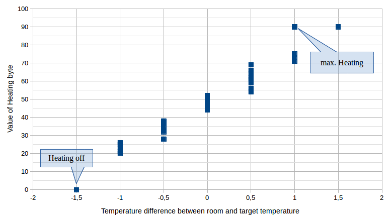
The values of this chart were observed for room temperatures of 22, 22.5, 23, 23.5 and 24°C, but the current room temperature has no influence on the heating byte, only the difference to the target temperature. As observed above, the same temperature difference can lead to different heating bytes, but apparently, the possible intervals for each temperature difference are not overlapping. This is an indication that the wireless control displays the temperature only in 0.5°C steps, but measures the current room temperature (and thus the difference to the target) in higher accuracy.
The possible (decimal) values of the byte range from 0 (for OFF) to 90 (for fully ON). So, are these percentage values (i.e. 0% heating to 90%) of the capacity of the boiler?
The final indication that we need to fully understand the byte can be found in the diagnosis mode of the control: The manual states that when diagnosis mode is initiated, the boiler will be instructed to heat the water for the heating to exactly 50° C. When enabling diagnosis mode (pressing the „P“ button and the knob together for 3 seconds), the following signal is sent by the remote:
0x00 00 7E 6D F6 00 20 00 00 80 32 00 FD CB FF 00


0x00 00 7E 6D F6 00 20 00 01 80 32 00 FD CA FF 00
So, the heating byte 0x32 corresponds to a heating water temperature of 50°C. If you are used to hex numbers, you probably already saw it. If not, let's just write the heating bit in decimal: 0x32 = 50. This can't be a coincidence! The heating byte must be the target temperature of the heating water.
This makes perfect sense: The values observed (for „normal“ room temperatures slightly above 20°C) are between 20 and 90 (decimal). Anything above 90°C for water is already dangerous considering the boiling temperature of 100°C.
If 2-point mode is enabled, bit 8 is set and bits 1-7 carry a value of 52°C, in analogue mode bit 8 is never set and bits 1-7 carry the target heating water temperature. So,
The Full Data Frame Specification
The data is sent in frames of 16 bytes, where the actual data is contained in bytes 4-12, and bytes 13-14 are a 2-byte checksum.
Summarizing our interpretation of the individual bytes of the signal:
| Byte | Value | Description | |
|---|---|---|---|
| 1-2 | 0x00 00 | Preamble (square wave to synchronize clocks with the receiver) | |
| 3 | 0x7E | Begin of frame/data (Constant) | |
| 4-14 | Data content of the frame with 2-byte checksum attached | ||
| 4-5 | 0x6D F6 | Device ID (Constant for each device) | |
| 6-8 | 0x00 20 00 | Unknown (constant, bit 6 of byte 7 always set) | |
| 9 | 0x00/01 | Repeat: 0x00 for original signal, 0x01 for repeat signal (bit 1) | |
| 10 | 0x80/88 | Pre-heated Water: 0x80 for ON, 0x88 for OFF (bit 8 always set, bit 4 indicates water) | |
| 11 | 0xB4/00/… | Heating: 0x00 for OFF, 0xB4 for ON, Target heating water temperatur for analogue mode | |
| 12 | 0x00 | Battery: 0x00 for OK, 0x01 for LOW (bit 1) | |
| 13-14 | 0xFD .. | 2-byte Checksum (signed integer): negative of the sum of bytes 4-12 | |
| 15 | 0xFF | End of Signal indicator | |
| 16 | 0x00 | Epilogue (no data any more) | |

All bytes are converted to a bit sequence with least-significant bit first.
For transmission over the 868,275MHz frequency, the data contents (bytes 4-14, but NOT bytes 3 and 15) are bit-stuffed (i.e. after five consecutive one bits, one extra zero bit is inserted). The resulting bit sequence is then encoded using differential Manchester encoding (1 is encoded as a transition, 0 as no transition) based on an underlying square wave of frequency 303Hz. Each bit period will be a half-wavelength, i.e. there will be 606 bit periods per second. After each bit period, a state transition is guaranteed and does not contain any information, and in the middle of each bit period there will be a state transition for a binary 1 and no transition or binary 0.
Each signal is first sent with byte 9 set to 0x00 and shortly afterwards repeated with byte 9 set to 0x01 (and the checksum updated correspondingly).
Setup Mode: RF detection
Playing around with the operator and installation modes of the Vaillant VRT340f, all signals I found fit perfectly well into the protocol described in the last section, except for one signal: RF detection:
0x00 00 7E FF FF 00 FF 00 F0 FF FF 6D F6 20 00 02 00 F8 90 FF 00


0x00 00 7E FF FF 00 FF 00 F1 FF FF 6D F6 20 00 02 00 F8 8F FF 00
As one can see, the signal is longer, but it still follows the same pattern of the begin and end of frame bytes. Also, bit-stuffing is still used, and the checksum is calculated just like in all other packets. However, there are some differences: the Device ID does not appear at the beginning of the data, but somewhere in the middle. Instead the device ID is 0xFF FF, which probably indicates a broadcast. All other values are completely unknown to me, as they never change.
| Byte | Value | Description | |
|---|---|---|---|
| 1-2 | 0x00 00 | Preamble (square wave to synchronize clocks with the receiver) | |
| 3 | 0x7E | Begin of frame/data (Constant) | |
| 4-19 | Data content of the frame with 2-byte checksum attached | ||
| 4-5 | 0xFF FF | Indicates broadcast | |
| 6-8 | 0x00 FF 00 | Unknown (constant) | |
| 9 | 0xF0/F1 | Repeat: 0xF0 for original signal, 0xF1 for repeat signal (bit 1, bits 5-8 always set) | |
| 10-11 | 0xFF FF | Unknown (constant) | |
| 12-13 | 0x6D F6 | Device ID of searching control (Constant for each device) | |
| 14-17 | 0x20 00 02 00 | Unknown (constant) | |
| 18-19 | 0xF8 .. | 2-byte Checksum (signed integer): negative of the sum of bytes 4-17 | |
| 20 | 0xFF | End of Signal indicator | |
| 21 | 0x00 | Epilogue (no data any more) | |
Implementing support for the device in rtl_433, rflink and/or OpenHAB
Now that we understand both the physical layer of the signal, as well as the structure of the protocol, we can go on to implementing support for it in applications like rtl_433 (part of GNUradio), rflink or OpenHAB in part 3 of our series.